Friday, April 22, 2016

Arduino with RFID

Arduino with RFID


#include
#include

#define uchar unsigned char
#define uint unsigned int

//4 bytes tag serial number, the first 5 bytes for the checksum byte
uchar serNumA[5];

uchar fifobytes;
uchar fifoValue;

AddicoreRFID myRFID; // create AddicoreRFID object to control the RFID module

/////////////////////////////////////////////////////////////////////
//set the pins
/////////////////////////////////////////////////////////////////////
const int chipSelectPin = 10;
const int NRSTPD = 9;

//Maximum length of the array
#define MAX_LEN 16

void setup() {                
   Serial.begin(9600);                        // RFID reader SOUT pin connected to Serial RX pin at 9600bps 

  // start the SPI library:
  SPI.begin();
  
  pinMode(chipSelectPin,OUTPUT);              // Set digital pin 10 as OUTPUT to connect it to the RFID /ENABLE pin 
    digitalWrite(chipSelectPin, LOW);         // Activate the RFID reader
  pinMode(NRSTPD,OUTPUT);                     // Set digital pin 10 , Not Reset and Power-down
    digitalWrite(NRSTPD, HIGH);

  myRFID.AddicoreRFID_Init();  
}

void loop()
{
  uchar i, tmp, checksum1;
uchar status;
        uchar str[MAX_LEN];
        uchar RC_size;
        uchar blockAddr; //Selection operation block address 0 to 63
        String mynum = "";

        str[1] = 0x4400;
//Find tags, return tag type
status = myRFID.AddicoreRFID_Request(PICC_REQIDL, str);
if (status == MI_OK)
{
            Serial.println("RFID tag detected");
      
}

//Anti-collision, return tag serial number 4 bytes
status = myRFID.AddicoreRFID_Anticoll(str);
if (status == MI_OK)
{
            checksum1 = str[0] ^ str[1] ^ str[2] ^ str[3];
          
           Serial.print(str[0]);
           Serial.print(" , ");
       Serial.print(str[1]);
            Serial.print(" , ");
       Serial.print(str[2]);
           Serial.print(" , ");
       Serial.print(str[3]);
            Serial.print(" , ");
       Serial.print(str[4]);
            Serial.print(" , ");
            Serial.println(checksum1,BIN);
            
            Serial.println();
            delay(1000);
}
        myRFID.AddicoreRFID_Halt();   //Command tag into hibernation              

}

Tuesday, February 16, 2016

Playing Ultrasonic sensor with Arduino


Playing Ultrasonic sensor with Arduino


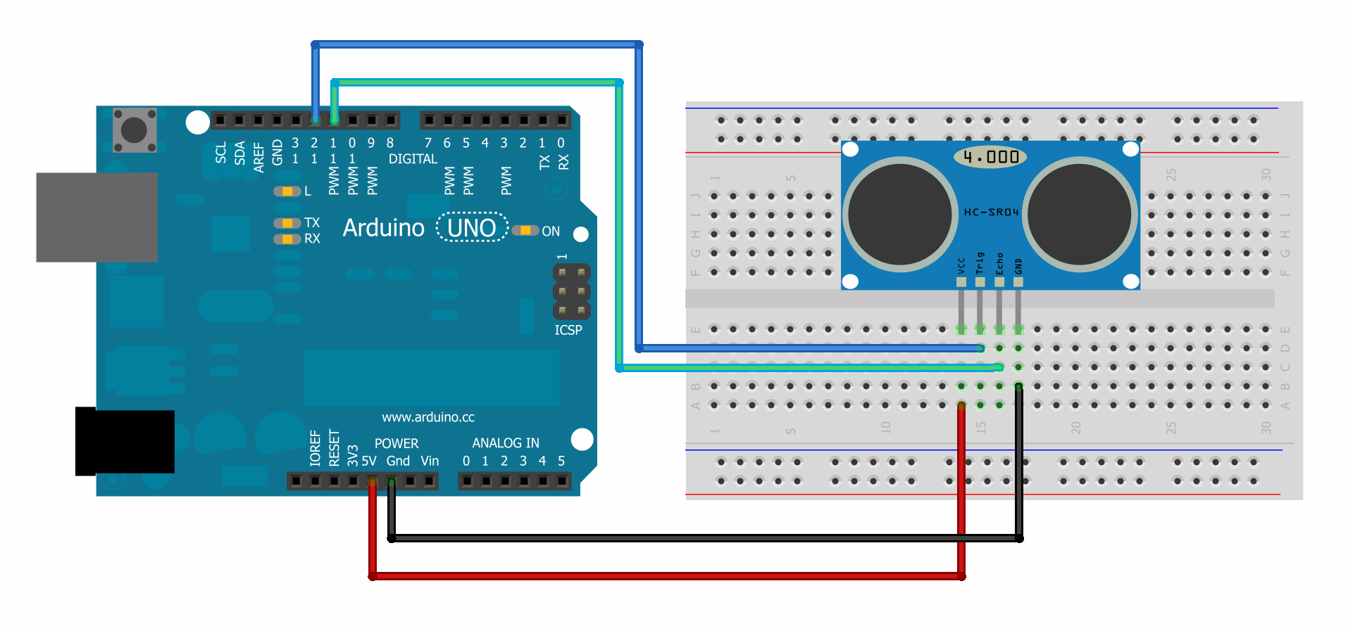
1. The Connection


1424201420-2wire_bb.png


2. The script

#define echopin 3
#define TRIGPIN 2

void setup()
{
  Serial.begin (9600);
  pinMode (echopin,INPUT);
  pinMode (TRIGPIN, OUTPUT);
}
void loop()

{ digitalWrite(TRIGPIN,LOW);
delayMicroseconds(2);
digitalWrite(TRIGPIN,HIGH);
delayMicroseconds(10);
digitalWrite(TRIGPIN,LOW);

float distance = pulseIn(echopin,HIGH);
distance = distance/46;
Serial.print (distance);
Serial.println (" cm");
if (distance < 10)
{
Serial.print("AWAS HATI-HATI");
Serial.println (" Jarak kurang dari 10 cm");
}
else if
 (distance < 20)
{
Serial.print("Waspada");
Serial.println (" Jarak kurang dari 20 cm");
}
else
{
  Serial.println ("Jarak Masih Aman");

}
delay (200);
}

playing with Gyro sensor GY-291 and Arduino


1. connection.


2. The Script

/* Include the standard wire library */
#include

/* Alternate I2C address of the module */
#define I2C_Add 0x53

/* ADXL345 register addresses */
#define POWER_CTL 0x2D
#define DATA_FORMAT 0x31
#define X_Axis 0x32
#define Y_Axis 0x34
#define Z_Axis 0x36

/* Accelerometer range modes */
#define RANGE_2g 0
#define RANGE_4g 1
#define RANGE_8g 2
#define RANGE_16g 3

void setup()
{
  /* Initialise the I2C bus */
  Wire.begin();  
  
  /* Initialise the serial interface */
  Serial.begin(9600);
  
  /* Initialise the ADXL345 */  
  Init_ADXL345(RANGE_2g);
}

/* Main program */
void loop()
{
  /* Continually read and output all 3 axis to the serial port */
  Serial.print("X: ");
  Serial.print(Read_Axis(X_Axis));
  
  Serial.print(" Y: ");
  Serial.print(Read_Axis(Y_Axis));
  
  Serial.print(" Z: ");
  Serial.println(Read_Axis(Z_Axis));
}

/* Read one of the 3 axis via the I2C interface */
int Read_Axis(byte axis)
{
  int Data;
   
  Wire.beginTransmission(I2C_Add); 
  Wire.write(axis); 
  Wire.endTransmission(); 
  
  Wire.beginTransmission(I2C_Add);
  Wire.requestFrom(I2C_Add, 2);
  
  /* If data is available then read it (2 bytes) */
  if(Wire.available())     
  { 
    Data = (int)Wire.read();
    Data = Data  | (Wire.read() << 8);
  }else
  {
    Data = 0;
  }
    
  Wire.endTransmission();  
  return Data;
}


/* Initialise the ADXL345 */
void Init_ADXL345(byte range)
{
  Wire.beginTransmission(I2C_Add);
  
  /* Set the sensitivity of the module */
  Wire.write(DATA_FORMAT); 
  Wire.write(range); 
  Wire.endTransmission(); 
  
  /* Put the module into measurement mode to start taking measurements */
  Wire.beginTransmission(I2C_Add);
  Wire.write(POWER_CTL); 
  Wire.write(0x08); 
  
  Wire.endTransmission(); 
}


Friday, February 5, 2016

Controlling arduino using serial openwrt

Controlling arduino using serial openwrt


1. Create sketch

// include the library code:
#include

// initialize the library with the numbers of the interface pins
LiquidCrystal lcd(7, 6, 5, 4, 3, 2);

void setup() {
  // set up the LCD's number of columns and rows:
  lcd.begin(16, 2);
  // initialize the serial communications:
  Serial.begin(9600);
}

void loop() {
  // when characters arrive over the serial port...
  if (Serial.available()) {
    // wait a bit for the entire message to arrive
    delay(100);
    // clear the screen
    lcd.clear();
    // read all the available characters
    while (Serial.available() > 0) {
      // display each character to the LCD
      lcd.write(Serial.read());
    }
  }
}

2. Upload the sketch
3. For testing the arduino ,open serial monitor, and type something.


4. Install modem driver on openwrt

root@OpenWrt:~# opkg install kmod-usb-serial kmod-usb-serial-ftdi

5. Attach Arduino to OpenWRT, and check on dmesg

[ 5182.260000] usb 1-1: new full-speed USB device number 3 using ehci-platform
[ 5182.430000] cdc_acm 1-1:1.0: ttyACM0: USB ACM device

6. Install coreutils-stty

root@OpenWrt:~# opkg install coreutils-stty

7. Add  this to /etc/rc.local before start
stty -F /dev/ttyACM0 4:0:18b2:0:0:0:0:0:1:0:0:0:0:0:0:0:0:0:0:0:0:0:0:0:0:0:0:0:
stty -F /dev/ttyACM0 9600 raw
=> Reboot router

8. Test from openwrt,

- open ssh to IP of openwrt
- type echo -en "Selamat Siang" > /dev/ttyACM0   than press enter.

9. Result on LCD screen.

Thursday, January 14, 2016

Playing with ESP8622

Playing with ESP8622


Pin Connection

ESP8622            USB-TTL

  GND     -------      GND
  VCC     -------      3.3V
  RX        -------       TX
  TX        -------        RX
 CH-PD  -------      3,3V

Open putty or serial communication software,


Sunday, December 6, 2015

Arduino with LCD


1. Create sketch

// include the library code:
#include

// initialize the library with the numbers of the interface pins
LiquidCrystal lcd(7, 6, 5, 4, 3, 2);

void setup() {
  // set up the LCD's number of columns and rows:
  lcd.begin(16, 2);
  // initialize the serial communications:
  Serial.begin(9600);
}

void loop() {
  // when characters arrive over the serial port...
  if (Serial.available()) {
    // wait a bit for the entire message to arrive
    delay(100);
    // clear the screen
    lcd.clear();
    // read all the available characters
    while (Serial.available() > 0) {
      // display each character to the LCD
      lcd.write(Serial.read());
    }
  }
}

2. Upload the sketch
3. open serial monitor, and type something.

Monday, November 23, 2015

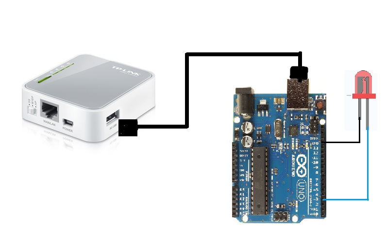
Control Led on Arduino using OpenWRT (TP Link MR-3020) serial com


1. Install modem driver on openwrt

root@OpenWrt:~# opkg install kmod-usb-serial kmod-usb-serial-ftdi

2. Attach Arduino to OpenWRT, and check on dmesg

[ 5182.260000] usb 1-1: new full-speed USB device number 3 using ehci-platform
[ 5182.430000] cdc_acm 1-1:1.0: ttyACM0: USB ACM device

3. Install coreutils-stty

root@OpenWrt:~# opkg install coreutils-stty

4. run coreutils

stty -F /dev/ttyACM0 cs8 9600 ignbrk -brkint -icrnl -imaxbel -opost -onlcr -isig -icanon -iexten -echo -echoe -echok -echoctl -echoke noflsh -ixon -crtscts

5. upload the sketch to Arduino.


int ledPin3 = 3;

int ledPin2 = 2;

int incomingByte;          // a variable to read incoming serial data into


void setup() {   

   Serial.begin(9600);     

   pinMode(ledPin3, OUTPUT);              

   pinMode(ledPin2, OUTPUT);              

}


void loop() {    

    if (Serial.available() > 0) {        // see if there's incoming serial data:

        incomingByte = Serial.read();     // read the oldest byte in the serial buffer

                                        //Preform the code to switch on or off the leds

        if (incomingByte == '1') {

            digitalWrite(ledPin3, HIGH);     //If the serial data is 0 turn LED 1 on

        }

        if (incomingByte == '2') {

            digitalWrite(ledPin3, LOW);     //If the serial data is 1 turn LED 1 off

        }

        if (incomingByte == '3') {

            digitalWrite(ledPin2, HIGH);     //If the serial data is 2 turn LED 2 on

        }

        if (incomingByte == '4') {

            digitalWrite(ledPin2, LOW);     //If the serial data is 3 turn LED 2 off

        }

    }

}

6. run this command on Openwrt terminal.

-- to turn on LedPin3

echo "1" >/dev/ttyACM0

-- to turn off Led 

echo "2" >/dev/ttyACM0


Image result for smiley face